- 制造厂商:TI
- 产品类别:放大器
- 技术类目:运算放大器 (op amps) - 高速运算放大器 (GBW ≥ 50MHz)
- 功能描述:70MHz 高速放大器
- 点击这里打开及下载THS4051M的技术文档资料
- TI代理渠道,提供当日发货、严格的质量标准,满足您的目标价格

The THS4051 and THS4052 are general-purpose, single/dual, high-speed voltage feedback amplifiers ideal for a wide range of applications including video, communication, and imaging. The devices offer very good ac performance with 70-MHz bandwidth, 240-V/us slew rate, and 60-ns settling time (0.1%). The THS4051/2 are stable at all gains for both inverting and non-inverting configurations. These amplifiers have a high output drive capability of 100 mA and draw only 8.5-mA supply current per channel. Excellent professional video results can be obtained with the low differential gain/phase errors of 0.01%/0.01° and wide 0.1 dB flatness to 30 MHz. For applications requiring low distortion, the THS4051/2 is ideally suited with total harmonic distortion of -82 dBc at 1 MHz.
- High Speed
- 70 MHz Bandwidth (G = 1, -3 dB)
- 240 V/us Slew Rate
- 60-ns Settling Time (0.1%)
- High Output Drive, IO = 100 mA (typ)
- Excellent Video Performance
- 0.1 dB Bandwidth of 30 MHz (G = 1)
- 0.01% Differential Gain
- 0.01° Differential Phase
- Very Low Distortion
- THD = -82 dBc (f = 1 MHz, RL = 150 Ω)
- THD = -89 dBc (f = 1 MHz, RL = 1 kΩ)
- Wide Range of Power Supplies - VCC = ±5 V to ±15 V
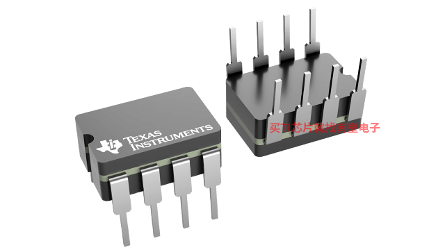
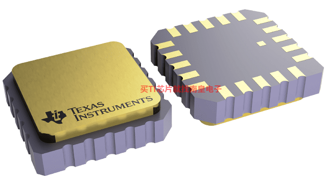
- Available in Standard SOIC, MSOP PowerPAD?, JG or FK Package
- Evaluation Module Available
DLP is a registered trademark of Texas Instruments. SMBus is a trademark of Intel Corp.
- Architecture
- Voltage FB
- Number of channels (#)
- 1
- Total supply voltage (Min) (+5V=5, +/-5V=10)
- 9
- Total supply voltage (Max) (+5V=5, +/-5V=10)
- 32
- GBW (Typ) (MHz)
- 70
- BW @ Acl (MHz)
- 70
- Acl, min spec gain (V/V)
- 1
- Slew rate (Typ) (V/us)
- 240
- Vn at flatband (Typ) (nV/rtHz)
- 14
- Vn at 1 kHz (Typ) (nV/rtHz)
- 14
- Iq per channel (Typ) (mA)
- 8.5
- Vos (offset voltage @ 25 C) (Max) (mV)
- 10
- Rail-to-rail
- No
- Rating
- Military
- Operating temperature range (C)
- -55 to 125
- CMRR (Typ) (dB)
- 100
- Input bias current (Max) (pA)
- 6000000
- Offset drift (Typ) (uV/C)
- 15
- Output current (Typ) (mA)
- 100
- 2nd harmonic (dBc)
- 82
- 3rd harmonic (dBc)
- 82
- @ MHz
- 1
THS4051M的完整型号有:5962-9959901Q2A、5962-9959901QPA、THS4051MFKB、THS4051MJG、THS4051MJGB,以下是这些产品的关键参数及官网采购报价:
5962-9959901Q2A,工作温度:-55 to 125,封装:LCCC (FK)-20,包装数量MPQ:1个,MSL 等级/回流焊峰值温度:N/A for Pkg Type,引脚镀层/焊球材料:SNPB,TI官网5962-9959901Q2A的批量USD价格:44.751(1000+)
5962-9959901QPA,工作温度:-55 to 125,封装:CDIP (JG)-8,包装数量MPQ:1个,MSL 等级/回流焊峰值温度:N/A for Pkg Type,引脚镀层/焊球材料:SNPB,TI官网5962-9959901QPA的批量USD价格:35.801(1000+)
THS4051MFKB,工作温度:-55 to 125,封装:LCCC (FK)-20,包装数量MPQ:1个,MSL 等级/回流焊峰值温度:N/A for Pkg Type,引脚镀层/焊球材料:SNPB,TI官网THS4051MFKB的批量USD价格:44.751(1000+)
THS4051MJG,工作温度:-55 to 125,封装:CDIP (JG)-8,包装数量MPQ:1个,MSL 等级/回流焊峰值温度:N/A for Pkg Type,引脚镀层/焊球材料:SNPB,TI官网THS4051MJG的批量USD价格:35.801(1000+)
THS4051MJGB,工作温度:-55 to 125,封装:CDIP (JG)-8,包装数量MPQ:1个,MSL 等级/回流焊峰值温度:N/A for Pkg Type,引脚镀层/焊球材料:SNPB,TI官网THS4051MJGB的批量USD价格:35.801(1000+)

PSPICE-FOR-TI — 适用于 TI 设计和模拟工具的 PSpice
PSpice for TI 可提供帮助评估模拟电路功能的设计和仿真环境。此功能齐全的设计和仿真套件使用 Cadence 的模拟分析引擎。PSpice for TI 可免费使用,包括业内超大的模型库之一,涵盖我们的模拟和电源产品系列以及精选的模拟行为模型。借助?PSpice for TI 的设计和仿真环境及其内置的模型库,您可对复杂的混合信号设计进行仿真。创建完整的终端设备设计和原型解决方案,然后再进行布局和制造,可缩短产品上市时间并降低开发成本。
在?PSpice for TI 设计和仿真工具中,您可以搜索 TI (...)
TINA-TI — 基于 SPICE 的模拟仿真程序
TINA-TI 提供了 SPICE 所有的传统直流、瞬态和频域分析以及更多。TINA 具有广泛的后处理功能,允许您按照希望的方式设置结果的格式。虚拟仪器允许您选择输入波形、探针电路节点电压和波形。TINA 的原理图捕获非常直观 - 真正的“快速入门”。TINA-TI 安装需要大约 500MB。直接安装,如果想卸载也很容易。我们相信您肯定会爱不释手。
TINA 是德州仪器 (TI) 专有的 DesignSoft 产品。该免费版本具有完整的功能,但不支持完整版 TINA 所提供的某些其他功能。
如需获取可用 TINA-TI 模型的完整列表,请参阅:SpiceRack - 完整列表
需要 HSpice (...)
ANALOG-ENGINEER-CALC — 模拟工程师计算器
模拟工程师计算器旨在加快模拟电路设计工程师经常使用的许多重复性计算。该基于 PC 的工具提供图形界面,其中显示各种常见计算的列表(从使用反馈电阻器设置运算放大器增益到为稳定模数转换器 (ADC) 驱动器缓冲器电路选择合适的电路设计元件)。除了可用作单独的工具之外,该计算器还能够很好地与模拟工程师口袋参考书中所述的概念配合使用。 lock = 需要出口许可(1分钟)VOLT-DIVIDER-CALC — 分压器确定一组分压电阻
VOLT-DIVIDER-CALC quickly determines a set of resistors for a voltage divider. This KnowledgeBase Javascript utility can be used to find a set of resistors for a voltage divider to achieve the desired output voltage. This calculator can also be used to design non-inverting attentuation circuits.(...)


